Update: This lsystem/Structure Synth code has now (March 2016) been incorporated into the Sverchok Generative Art node. See the updated examples and the node docs
In the previous post I introduced the Sverchok scripted node I'd written to implement Structure Synth generative art or lsystems inside Blender.
In this post I'll cover a couple of features I've added to the basic node.
Mask output
An xml rule set for the lsystem can have different objects in different instances. In the xml below there are two versions of the "R1" rule. These will be called randomly. The two different rules have opposite signs for the "ry" transform. This will cause wobbles in the structure. When it wobbles one way "s1" is added to the list of shapes and when it wobbles the other way "s2" is added.
<rules max_depth="20">
    <rule name="entry">
        <call count="100" transforms="rx 3.6" rule="R1"/>
    </rule>
    <rule name="R1">
        <call transforms="sa 0.9 ry 6 tz 1" rule="R1"/>
        <instance transforms="s 0.2 0.5 1" shape="s1"/>
    </rule>
    <rule name="R1">
        <call transforms="sa 0.9 ry -6 tz 1" rule="R1"/>
        <instance transforms="s 0.2 0.5 1" shape="s2"/>
    </rule>
</rules>
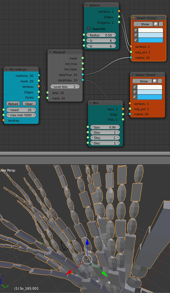
The names of these objects don't matter, they can be called anything in the xml.LSystem_blender.py passes the names to the node as strings. The node then converts these strings to integers (that is (0, 1) for two different objects, (0, 1, 2) for three objects etc.). This mask can be used as input to a "Mask List" node to separate the matrices into two lists as shown below. This is simple for two objects but is a bit more complicated but doable for more.
The "Levels List" on the "Mask List" node needs to be set to "2". That is because the outputs of the GA_node have been set up as a 2 level list. The first level corresponds to each arm of sub-part of the structure. The second level contains the actual output values. Examine the output with a "Viewer Text" node to help understand this.
Mesh output
Using the matrices output allows a separate object to be placed at each location. The vertices input and the mesh (vertices, edges, faces) output "skins" the mesh into a much smaller number of objects. The vertices input should be a list of vertices such as that generated by the "Circle" node. It could also be a circle type object taking from the scene using the "Objects In" node. The list of vertices should be in order so they can be made into a ring with the last vertex joined to the first. That ring dosen't have to be planar.
If the vertices are taken from an object in the scene the vertices can be repositioned in "EDIT" and the structure updated by going to "OBJECT" mode then clicking the "Update Node Tree" button.
The output will not always be one mesh. If the rule set ends one 'arm' and goes back to start another 'arm' these two sub-parts will be separate meshes. Sometimes the mesh does not turn out how you would like. This can often be fixed by changing the rule set.
Often a mesh tube will turn out flat rather than being tube like. This can usually be fixed by either rotating the vertex ring in the scene or by adding a rotation transform to the "instance" commands in the rule set.
For example change <instance shape="s1"/> to <instance transfroms="ry 90" shape="s1"/>
In other cases the mesh can be connected in the wrong order.
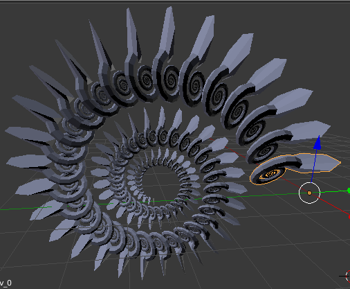
My first attempt at the Fern structure had this effect.
<rules max_depth="2000">
    <rule name="entry">
        <call  rule="curl" />
    </rule>

    <rule name="curl" max_depth="80">
        <call transforms="rx 12.5 tz 0.9 s 0.98 0.95 1.0" rule="curl"/>
        <instance shape="box"/>
        <call transforms="tx 0.1 ty -0.45 ry 40 sa 0.25" rule="curlsmall" />
    </rule>

    <rule name="curlsmall" max_depth="80">
        <call transforms="rx 25 tz 1.2 s 0.9 0.9 1.0" rule="curlsmall"/>
        <instance shape="box"/>
    </rule>

</rules>
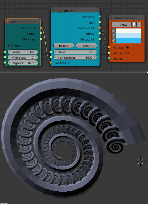
The following xml produces the result I was after that's shown with the node diagram above.
<rules max_depth="2000">
    <rule name="entry">
        <call  rule="curl1" />
        <call  rule="curl2" />
    </rule>

    <rule name="curl1" max_depth="80">
        <call transforms="rx 12.5 tz 0.9 s 0.98 0.95 1.0" rule="curl1"/>
        <instance shape="box"/>
    </rule>

    <rule name="curl2" max_depth="80">
        <call transforms="rx 12.5 tz 0.9 s 0.95 0.95 1.0" rule="curl2"/>
        <call transforms="tx 0.1 ty -0.45 ry 40 sa 0.25" rule="curlsmall" />
    </rule>

    <rule name="curlsmall" max_depth="80">
        <call transforms="rx 25 tz 1.2 s 0.9 0.9 1.0" rule="curlsmall"/>
        <instance shape="box"/>
    </rule>
</rules>
Both sets of xml rules produce the same list of matrices just in a different order.
The mesh output is very useful as further mesh operations or modifiers such as "Subdivision Surface" can then be used. Sub meshes can be joined together (CTRL-J) or booleans are sometimes successful if a single mesh is really required.