The same backtracking algorithm that produces 2D mazes can be used to produce three dimensional mazes. All that's needed is to set up the cells in the grid with an extra dimension and define the neighbors to include cells on the layers above and below the cell.
Here I've chosen the neighbors to be the 4 adjacent cells on the same layer, the 4 cells above these adjacent cells and the 4 cells below them. This gives each cell 12 neighbors and allows the maze to be drawn with ramps or diagonal staircases. This configuration is good for marble runs and mazes to explore in a game environment. A more common alternative would be to just add the cells directly above and below the original cells to give only six neighbors. This would require staircases going directly up from one level to the next.
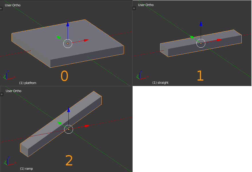
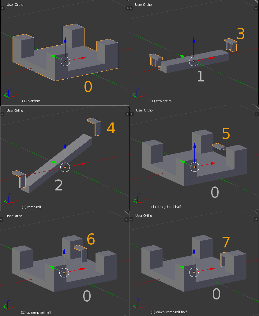
With 12 potential neighbors its impractical to include a different tile for each possible combination of links (as we did with the 2D maze). For 12 neighbors there would be \(2^{12} - 1 = 4095\) different tiles needed most of which would not occur in any given maze. Instead I've limited the maze components to a platform that sits at the center of each cell, a straight bridge that goes to a linked neighbor on the same level and a ramp that either goes up to the platform diagonally above or below the cell.
As before the python and blend files are on github.
Add maze_passage_3D.py and maze_3D.py as text blocks to a blender file. Set up a scripted node to use maze_passage_3D.py. Alternatively load maze_3D_demo.blend.
The node parameters are similar to the 2D version.
rseedsets the random number generator. Change to get a maze with a different path.sizeX, sizeY, sizeZset the size of the maze. SettingsizeZto 1 will produce a 2D maze.scaleXYsets the horizontal spacing of the maze components. It should be equal to the horizontal dimension of a plaform plus a bridge.scaleZsets the vertical spacing of the components and should be equal to the Z dimension of the ramp or staircase.braidset the proportion of dead ends to loops in the maze. Set to 0 there will be dead ends and no loops. There will only be one path between any two platforms in the maze. Set to 1 there will be lots of loops and no dead ends. Each platform will be connected by at least two bridges or ramps.
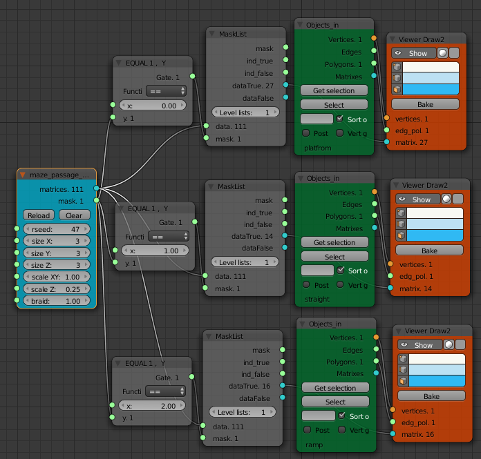
The matrices output gives a list of matrices define the location, and rotation of each maze component. The mask output gives a list of integers which define which component to place with each matrix.
- 0 : platform
- 1 : bridge
- 2 : ramp
- 3 : missing bridge rail (internal)
- 4 : missing ramp rail (internal)
- 5 : missing bride rail (edge)
- 6 : missing up ramp rail (edge)
- 7 : missing down ramp rail (edge)
Only the first 3 components are needed to produce a maze. I'll explain the other 5 components later. The platform component needs to have its origin at (0, 0, 0). The bridge component should also be centered at the origin. The ramp should also have its origin at (0, 0, 0) and needs to go upward from -X to + X. The ramp mesh needs to be offset from its origin in the y-direction. When the up ramp mesh is rotated 180 degrees around its origin it should be in the correct position to function as a down ramp without intersecting with either the up ramp or the bridge. A picture of a the simplest mesh for each component should make this clear.
It is possible to move the mesh of the bridge and ramp components relative to their origins (in edit mode) to get different configurations. For example the bridges could be set to be at the end of the platforms.
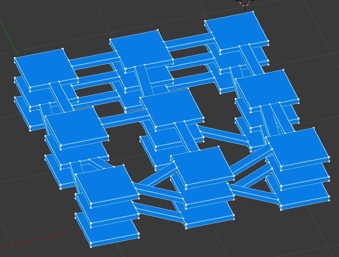
The lack of rails on the platforms above is a serious health and safety issue. To address this the additional matrices corresponding to the mask values 3 to 7 can be used to apply rails to the platforms where there is no link to another platform. For example the following components give the accompanying maze. Components 5, 6 and 7 are used at the edge of the maze while components 3 and 4 fill in the gaps in the middle of the maze. For a different look a broken bridge or a blocked passage way could be used instead of rails.
The extra edge rail components could also be used to place windows in a house maze. The internal rail components (3, 4) would be walls in the rooms.
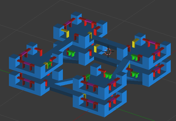
The screen shot at the top of the post is from red_maze_blue_maze.blend where more complex meshes have been used for the components. Three different objects have been used for the platforms to give some variation to the maze look. The matrix list was split into three random parts using List Shuffle, List Split and List Slice nodes.
Laser Blaster provided the template for the awesome player character I've used in the game. It's available from this blender artists post with a use it however you like license.
This red_maze_blue_maze.blend file is playable as a blender game with unlimited mazes to solve. Generate your own level (set the size and rseed values). Move the Spawn Here empty to the desired start point and the flag to the end point. Then just play (P). The character is moved with the WASD keys and the camera view can be moved around using the mouse (press the middle mouse button to activate).
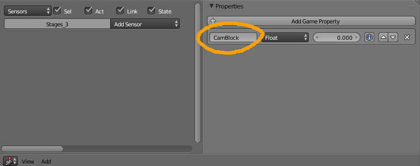
The camera view gets blocked by the geometry. This can be fixed by giving the Game Logic property CamBlock to any geometry you want the camera to avoid. The easiest way to do this is select all the maze components, join them together (CTRL-J) then in a Logic Editor view on the properties panel click the Add Game Property and type CamBlock in the field.