Last post I covered drawing geodesic lines (they look like circle arcs) on the Poincaré Disk. This time I’m going to cover drawing hyperbolic tilings. See this blend file for the node groups and assets.
Circle Inversion
The next maths step is finding the reflection of a point in the geodesic. Inversive geometry - Wikipedia
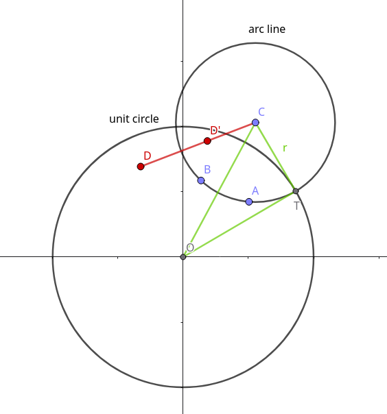
In the above diagram $D^\prime$ is the point $D$ reflected in the arc-line circle. $D^\prime$ lies on the line $CD$, where $C$ is the centre of the arc-line circle (coordinates $(x_0, y_0)$). The inversion position of this point along the line is defined such that :
\[|CD| \cdot |CD^\prime| =r^2\]or in coordinate geometry:
\(m = \frac{r^2}{(x-x_0)^2 + (y-y_0)^2}\)\(x^\prime = x_0 + m(x-x_0)\) \(y^\prime=y_0+m(y-y_0)\) or in math formula extension syntax:
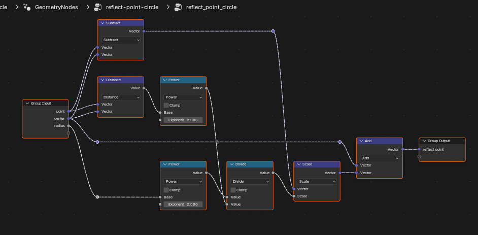
ng reflect_point_circle(point:vec3, center:vec3, radius:float)-> reflect_point:vec3 {
 m = radius**2.0/(dist(point, center)**2.0);
 d = sub(point, center);
 out reflect_point = center + scale(d, m);
 }
 reflect_point_circle({0.5, 0.5, 0.0}, {0.,0.,0.}, 1.0);
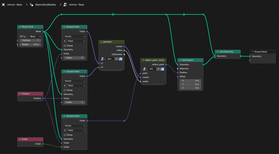
I end up with this node group.
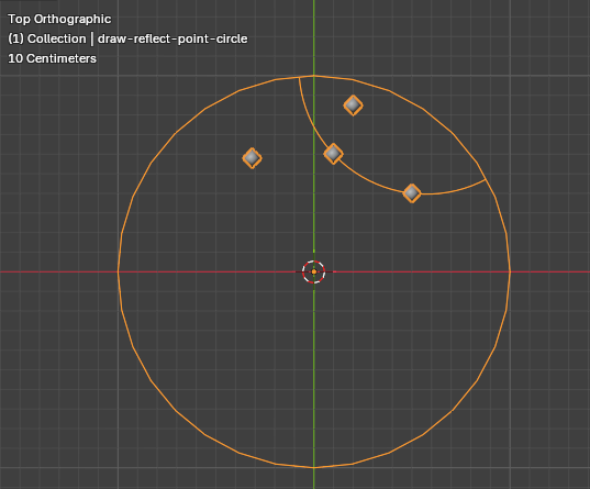
Check this by drawing a diagram similar to the GeoGebra one above.
Mirror a single face in the edge of a polygon
Next lets mirror an entire face in the circle.
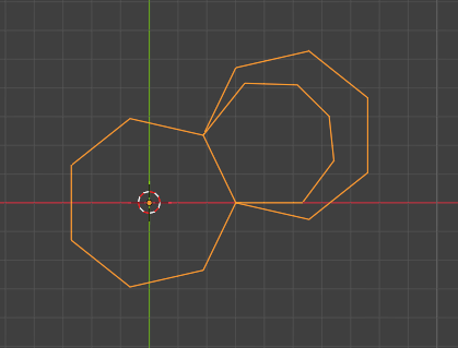
The smallest 7-gon is the mirror image of the central 7-gon in one of its edges using circle inversion. For comparison, the euclidean reflection is also shown.
Calculate the size of the central polygon
The central polygon of a hyperbolic tiling must have a specific radius $d$ depending on $p$ the number of vertices of each polygon, and $q$ the number of polygons (or edges) meeting at each vertex.
\[d = \sqrt{ \frac{ \tan\left( \frac{\pi}{2}-\frac{\pi}{q} \right)-\tan\left( \frac{\pi}{p} \right) } { \tan\left( \frac{\pi}{2} - \frac{\pi}{q} \right) + \tan\left( \frac{\pi}{p}\right) } }\]see Non-Euclidean Geometry: Interactive Hyperbolic Tiling in the Poincaré Disc for a derivation of this.
Math formula extension syntax
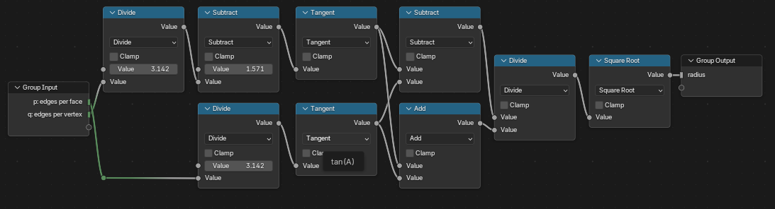
ng radius_center_n_gon(p:int, q:int) -> euclidean_radius: float {
	tq=tan(#(pi/2)-#pi/q);
	tp=tan(#pi/p);
	out euclidean_radius = sqrt((tq-tp)/(tq+tp));
}
radius_center_n_gon(7, 3);
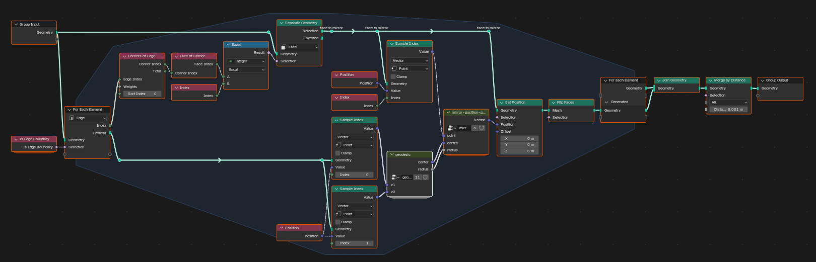
Mirror the adjacent face for all boundary edges
Next I wrap this up as a group that loops over all boundary edges, finds the adjacent face and reflects it in the edge.
Tiling
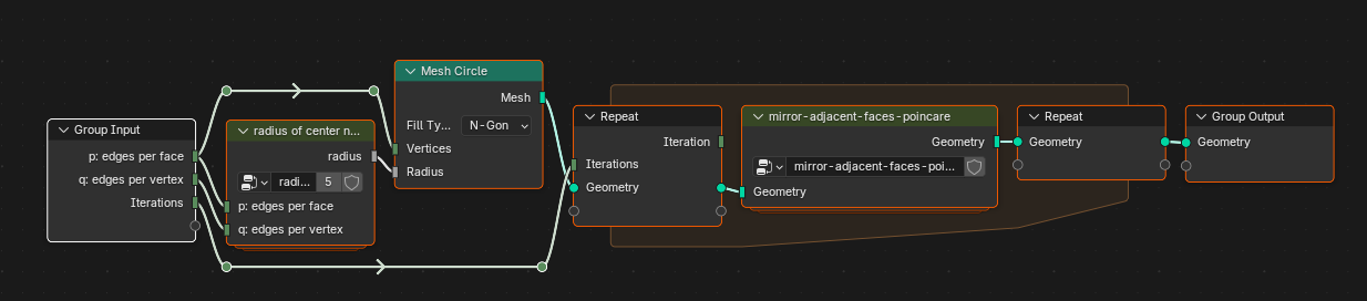
Combining all these steps to create a tiling of the Poincaré Disk. Recap Groups created - names as in the accompanying blend file.
- “geodesic” - find the centre and radius of the geodesic through two points on the Poincaré Plane
- “reflect-point-circle” - find the position of a point mirrored in a geodesic
- “radius-center-n-gon”
- “mirror-adjacent-faces-poincare” - mirror - the adjacent face for all boundary edges
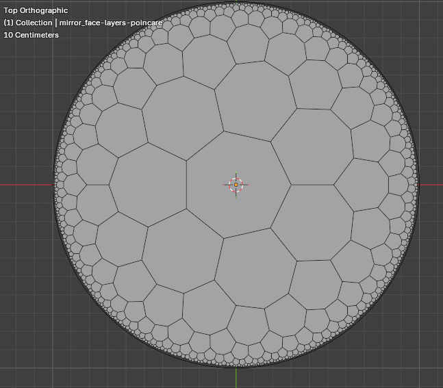
For ease, the edges of the polygons are plotted as a straight lines. They should, of course, be arcs. I’ll look at replacing the edges with geodesic segments in Part 3 of this series. In that post I’ll also show how to move the start polygon away from the centre.
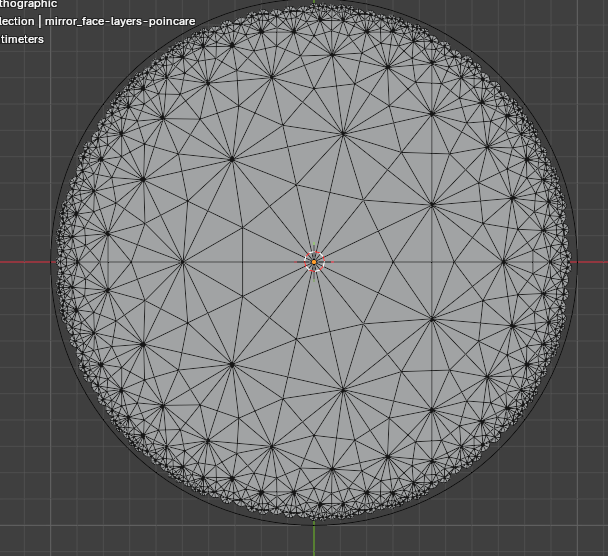
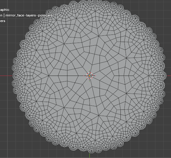
Subdividing tiling
Lots of fun can be had by adding triangulate, dual, and subdivide nodes to the tiling output.
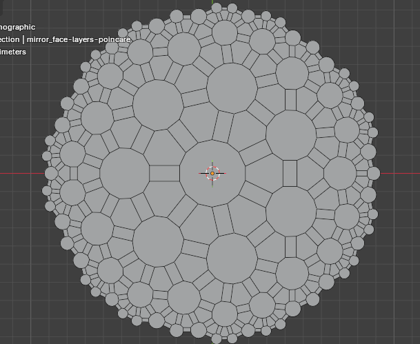

This is related to Conway Operators which is another thing I’ve been playing with in Geometry Nodes. I’ll write it up here eventually.