I’ve made several serious efforts to really learn the depths of Blender’s Geometry Nodes. I was really into Sverchok for a while, but I’ve found Geometry Nodes harder. Maybe its the moving target as more nodes are added. Maybe without a scripting node I can’t cheat and just wrap code in a node front end. I have a bit more time lately and I think I’m starting to make progress.
My learning strategy was to make a list of all the available nodes and work through them in groups (for example, all the mesh topology nodes) and make a trivial or simple node example for each. Currently I’ve done about 40% of the nodes in Blender 5.1. I might tidy this up and share at some point.
I mixed the node by node examples with trying to develop problems to solve that interested me. Watching endless rounds of you-tube videos, wire this node to that node, didn’t work for me.
I previously created Poincaré tilings in Sverchok way back in 2015. Then I was mostly interested in producing a 3D model of the hyperbolic plane by unfurling the tiling using Processing.
I was absolutely stoked when an image from the original blog was used on the cover of the journal “For the Learning of Mathematics” (Vol 39, No 1 (2019)). The issue included an article recalling the late David W. Henderson a mathematician who did extensive work alongside his wife Daina Taimina on the topology of hyperbolic planes.
This time, I’ll start by creating some node groups to do the basics such as drawing lines and circles and calculating distance in the Poincaré disc model. Then I’ll combine them to draw some pretty patterns including tilings.
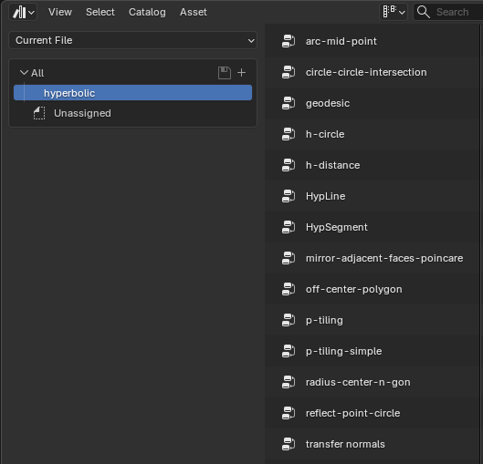
All the node groups are available as assets in a blend file . Refer to them if the screenshots I use below are a bit small.
I started an unpublished version of this post that had a lot of maths and derivations. This version I’m mostly going to quote the formula for each node group and give a reference to more detail.
What is the Poincaré disk?
A Euclidean plane is flat (zero curvature) and can be tiled with 6 hexagons surrounding a central hexagon. If you put 5 hexagons around a pentagon you get a sphere (positive curvature) like a soccer ball. If you put 7 hexagons around a heptagon (7 sided p-polygon) you get a hyperbolic plane with negative curvature everywhere. I describe it better (with pictures) in Blender Adventures with Hyperbolic Planes
The Poincaré disk is a model of the wrinkly 3D surface of a hyperbolic plane drawn flat on a 2D unit disk. All points on the hyperbolic plane are mapped on to a 2D disc with a radius of 1.
To get a feel for the weird geometry where straight lines are circular arcs have a play in the interactive tilings at Non-Euclidean Geometry: Interactive Hyperbolic Tiling in the Poincaré Disc and Make Hyperbolic Tilings of Images
Basic Tools
I’ve divided this post into three parts. The node groups I’ll describe in each post (blend file) are shown here.
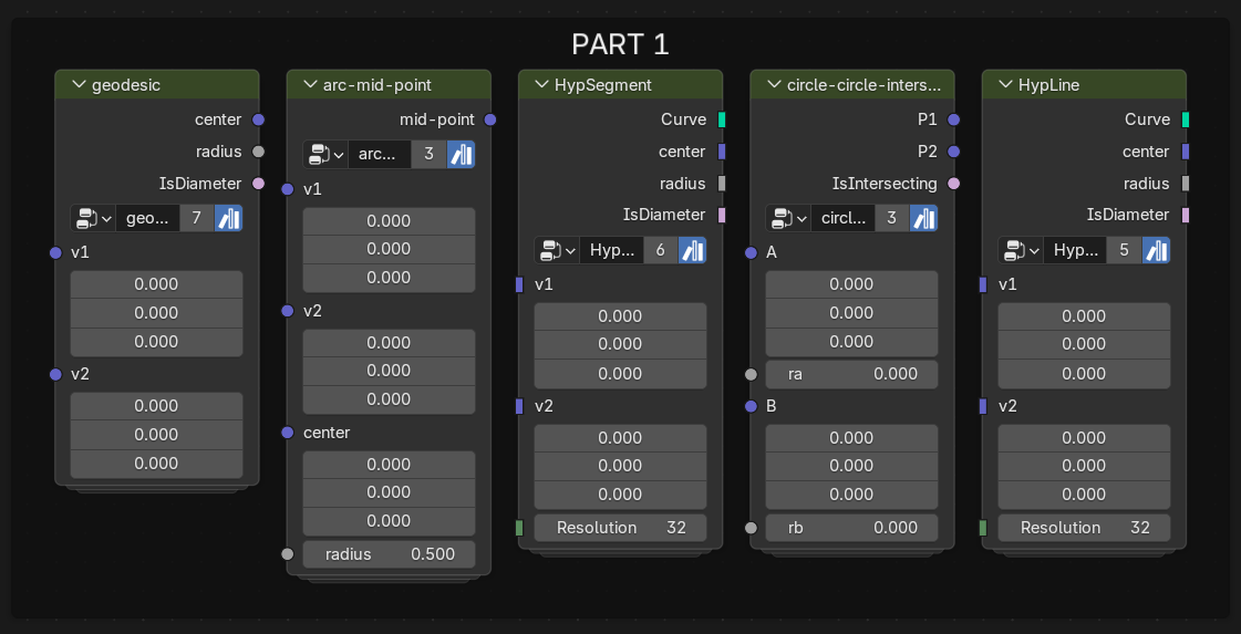
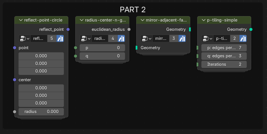

These are all available as assets in the blend file.
geodesic node group
The first step in creating a tiling on the Poincaré Disk, is to draw a line (called a geodesic) through two points. In this non-euclidean geometry this is a circle arc that goes through the two points $(a_x, a_y)$, $(b_x, b_y)$ and is perpendicular to the unit circle at the edge of the disk. If the geodesic goes through the origin, its a straight line diameter.

The geodesic node group returns the Euclidean centre and radius of the geodesic through two points, input as 3D vectors. If the two points are on a diameter the Is diameter? output is true, In this case, the centre is set to (0.0, 0.0, 0.0) and the radius is large. The centre and radius are in Euclidean space so can be used to draw lines and segments (see HypLine and HypSegment groups)
For all these node groups be sure to keep the z-component of the input vectors set to 0.0. The nodes internally use maths that assumes this.
The formulae for the Euclidean centre $(e_x, e_y)$ and radius $r$ are: \(e_x = -\frac{1}{2}\frac{a_y(b_x^{2}+b_y^{2} + 1) - b_y(a_x^{2}+a_y^{2} +1)}{a_x b_y-a_y b_x}\)
\(e_y = -\frac{1}{2}\frac{b_x(a_x^{2}+a_y^{2} + 1) - a_x(b_x^{2}+b_y^{2} +1)}{a_x b_y-a_y b_x}\) \(r=\sqrt{e_x^{2}+e_y^{2}-1}\)
These can be worked out from the formulae in the “By Analytical Geometry” section of the wikipedia artice on the Poincaré disk model.
Noding this up is prone to errors (as is typing in the Latex here). For the noding I used the Math Formula extension, which I highly recommend.
Use the shortcut ALT-F and copy paste the following.
ng geodesic(v1: vec3, v2: vec3) -> center:vec3, radius: float, IsDiameter: bool {
 ax, ay, _ = separate_xyz(v1);
 bx, by, _ = separate_xyz(v2);
 cx, cy, c = cross(v1, v2);
 sv1 = length(v1)**2.0+1.0;
 sv2 = length(v2)**2.0+1.0;
 ex = -0.5*(ay*sv2-by*sv1)/c;
 ey = -0.5*(bx*sv1-ax*sv2)/c;
 r = sqrt(ex**2.0 + ey**2.0 -1.0);
 out center = {ex, ey, 0.0};
 out radius = r;
 out IsDiameter = c == 0;
}
geodesic({0.5,0.,0.}, {0.,0.5,0.});
On hitting CTRL-ENTER you should magically get a new node group with ~ 27 nodes.
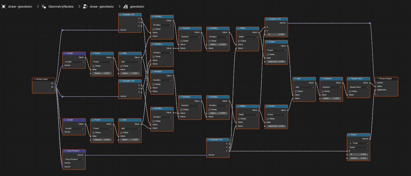
The Math Formula is a life saver for this kind of complicated maths.
Drawing geodesics
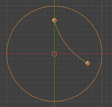
To draw the geodesic, The simplest is to translate a Mesh Circle using the center output of the geodesic node and scale using the radius output.
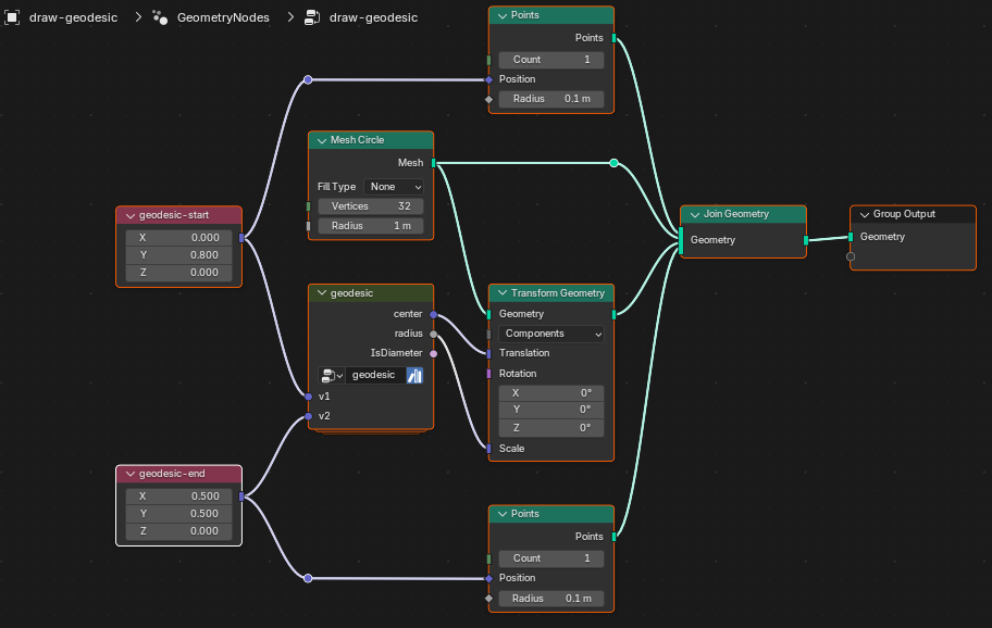
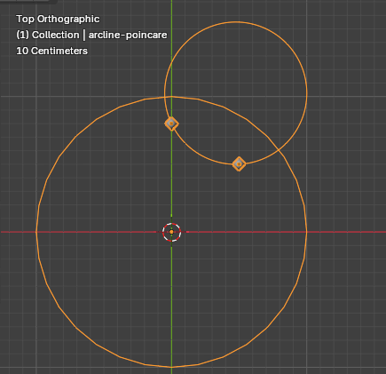
Moving the x, y coordinates of the line start and end should move the arc around. It should always be through the two points and cross the unit circle at right angles.
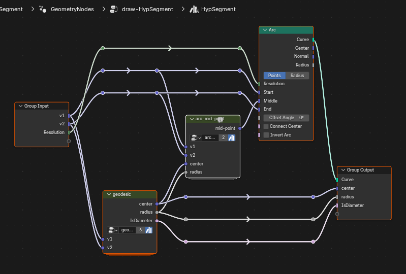
To draw a geodesic just between the two points I’ll use the Arc curve node.
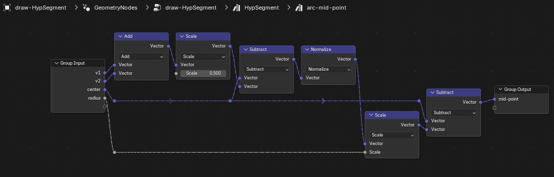
arc-mid-point node group
The “Arc” node (in Points mode) needs a mid point on the arc. I need to find Point E in the diagram below.
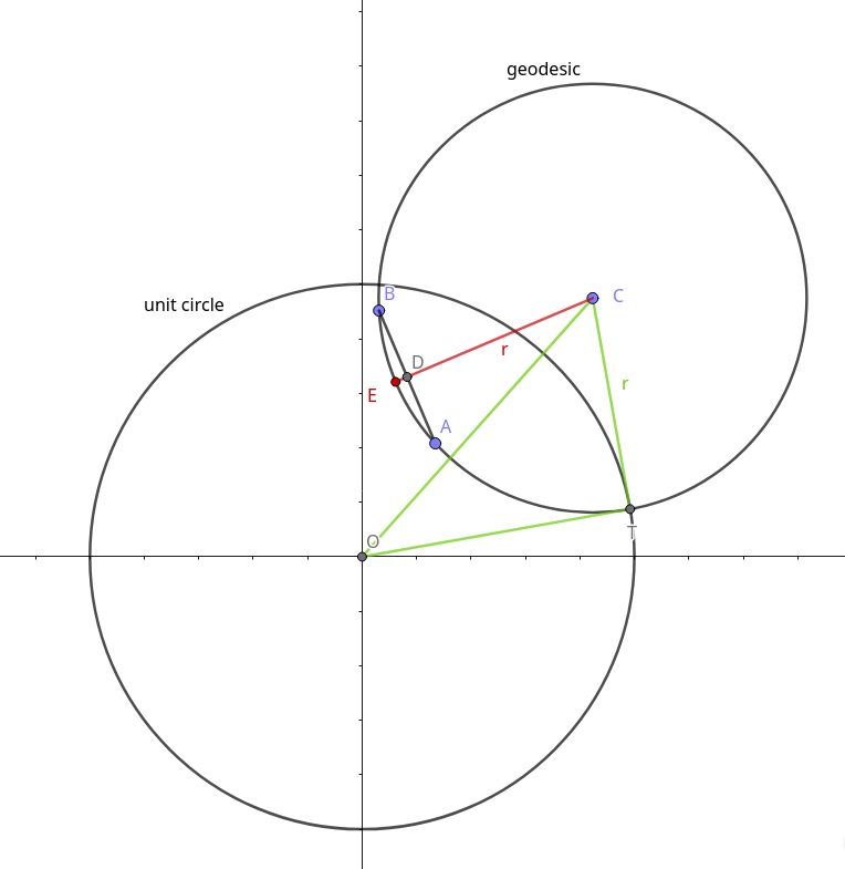
Some vector maths gives us:
\(\overline{OD} = \frac{\overline{OA} + \overline{OB}}{2}\)
\(\overline{OE} = \overline{OC} - \frac{\overline{OC}-\overline{OD}}{\Vert \overline{OC}-\overline{OD} \Vert} r\)
or as a node group - arc-mid-point
HypSegment node group
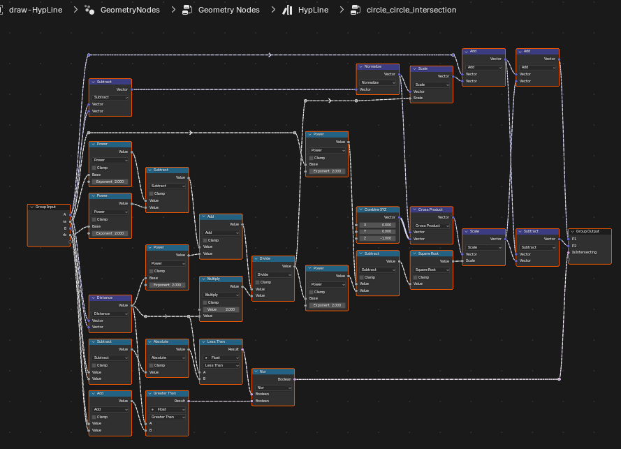
circle-circle-intersection node group
A full line on the Poincaré plane should start and end on the unit circle. To draw this, I need to find the two intersection points of the circle given by the geodesic node group and the unit circle. These are called the ideal points of the geodesic.
I made a node group for the intersection of any two circles as it will be useful later.
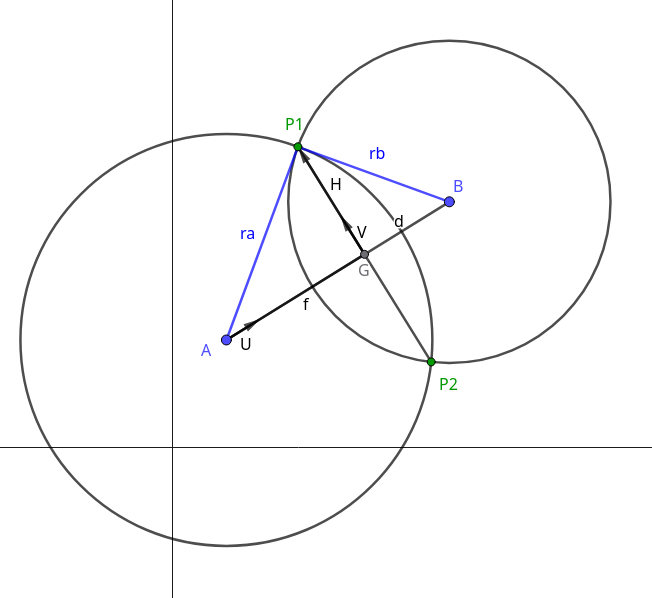
Here’s the math formula extension notation for that node group. The derivation can be found here for example. The symbols in the diagram match the code, uppercase for vectors, lowercase for scalars.
ng circle_circle_intersection(A:vec3,ra:float, B:vec3, rb:float) -> P1:vec3, P2:vec3, IsIntersecting: bool {
	d = dist(A, B);
	U = normalize(B-A);
	V = cross(U, {0.,0.,-1.});
	f = (ra**2.0 - rb**2.0 + d**2.0) / (2*d);
	G = A + scale(U, f);
	H = scale(V, sqrt(ra**2.0 - f**2.0));
	out P1 = G + H;
	out P2 = G - H;

	sr = ra + rb;
	mr = abs(ra - rb);
	out IsIntersecting = boolean_math_nor(d < mr, d > sr);
	}
circle_circle_intersection({0.,0.,0.}, 2., {1.,0.,0.}, 1.);
HypLine node group
This is similar to the HypSegment node group with the addition of the circle-circle-intersection group.
Pretty Pictures
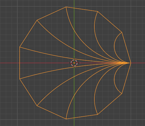
To end this post lets draw the geometry for the header image.
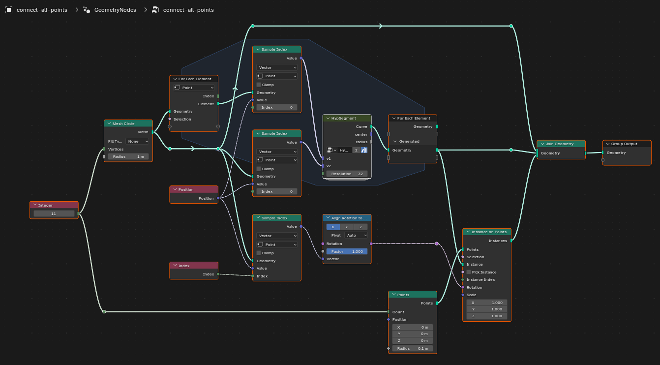
First connect one point of a mesh circle to all the others via a HypLine.
If we then instance this pattern on every point, we’ll double up a lot of curves, which show as texture artefacts when I convert the curves to a tube.
There are a couple of different ways to do this. Only draw half the lines in the for each element loop, then instance that on all points.
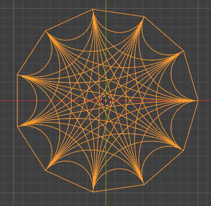
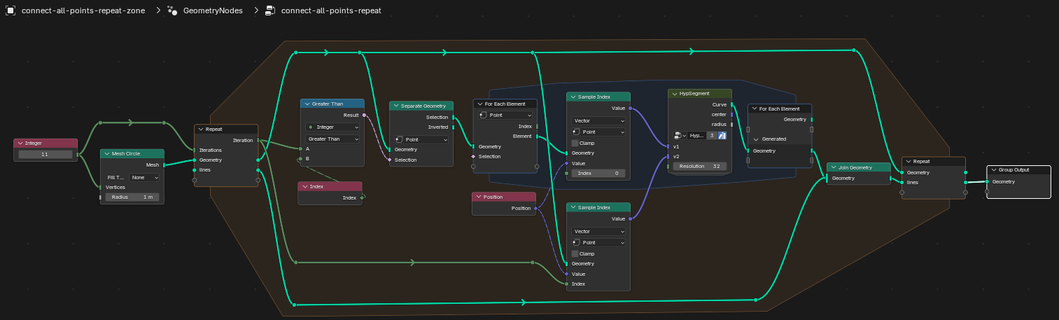
Or put a repeat zone around the for element zone
The blend file for this post is available.
Next post, I’ll cover circle inversion or mirroring across the geodesic leading to hyperbolic tilings.