My previous post introduced some of the basic concepts of Sverchok via the "Centers Polygons" node.
Here we'll try to gradually increase the complexity of our node diagram to do some more interesting things. Things that become increasingly harder to do outside Sverchok without using Blender python directly.
Last time we made a simple node diagram that copied one object of the scene onto the centers' of the polygons of another object in the scene. How would we apply a different scale to each of the copied objects? This scale could be random or structured in some way.
We know from playing last time with the "Matrix Out" and the "Text Viewer" node that the scale information is stored in the objects transform matrix. The "Centres Polygon" node produces a list of transform matrices for each of the copied objects. So to scale each object we going to intercept this list of matrices on its way from the "Centers Polygons" node to the "Viewer Draw" node.
A look around the nodes available finds a "Scale" node under Transforms and a "Matrix Deform" node under Matrix.
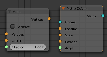
The "Scale" node has vertices as inputs and outputs. This would be useful for scaling the vertices of a single object (think of working in "EDIT" mode) but isn't for working with the transform matrices (think of working in "OBJECT" mode).
The "Matrix Deform" node looks more what we want. It has matrix (blue) inputs and outputs and further inputs for location, scale, rotation and angle. To apply an individual scale to each object we need a vector (x, y, z) for each object. This is produced in the next diagram with a "Vector" node and a "Random" node. The X and Y scales are set to 1 and the Z scale is connected to "Random" node. The "Random" node produces uniformly distributed numbers of the interval [0, 1]. This node diagram randomly scales each of the copied objects in their Z directions (along the normal of the polygon they've been copied to).
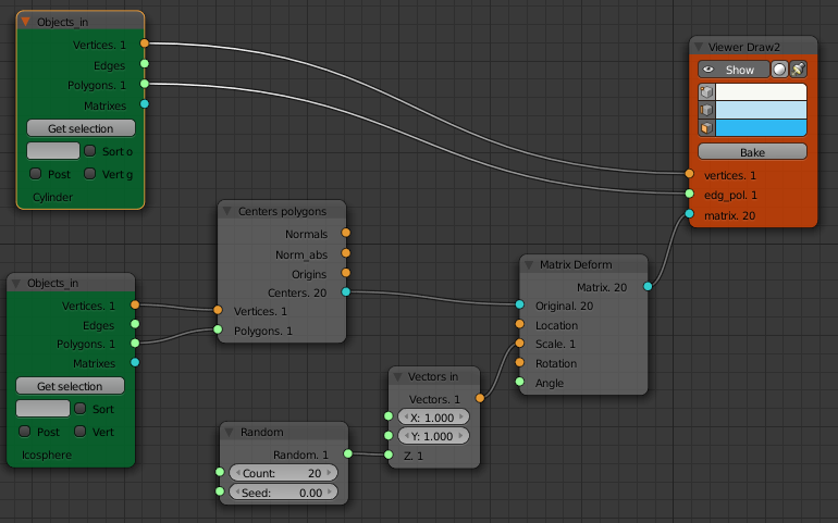
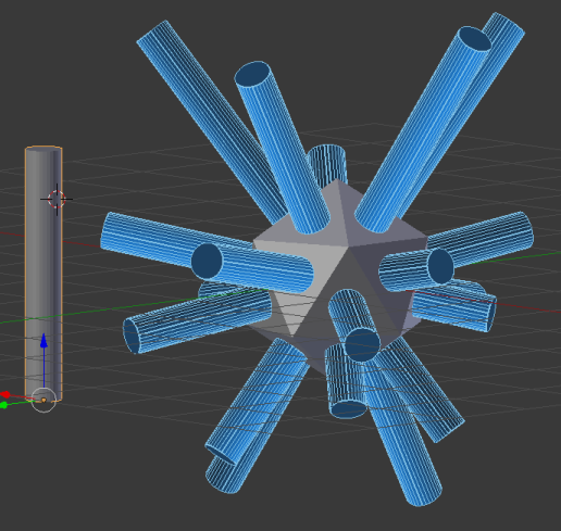
Here we have set the "Count" of the "Random" node to 20 as we know that's how many faces our mesh has. If we change the mesh it would be nice if this updated automatically to the number of polygons in the mesh. This is done via the "List Length" node as shown below.
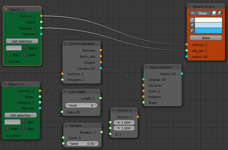
What if we wanted to scale the spike objects in a more structured way? Its just a matter of getting a list of scale vectors of the right length and feeding them to our matrix deform node.
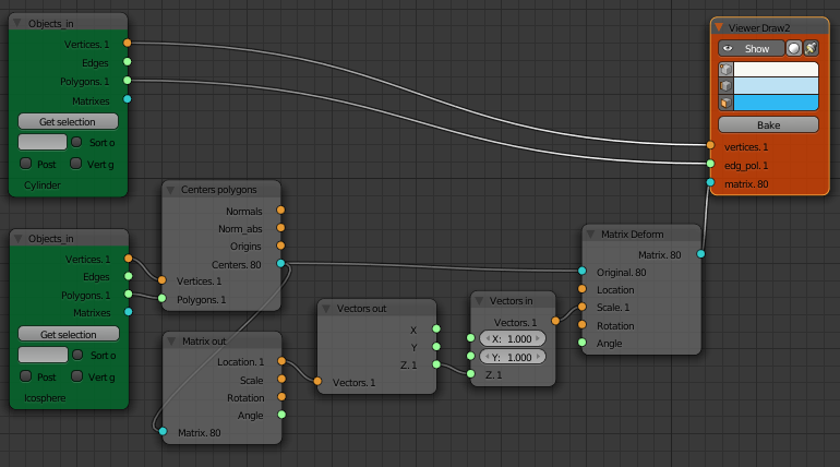
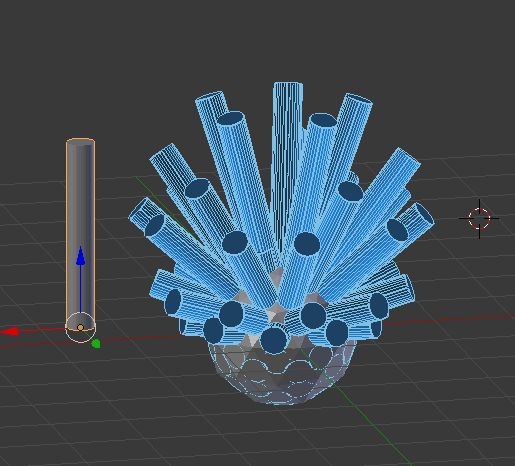
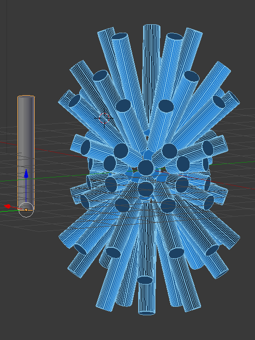
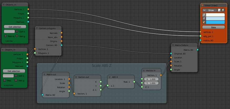
Here we've scaled the length of the cylinders by the z location of the polygon the cylinder is copied to. This is done by using a "Matrix Out" node to separate out the location of the center of each polygon, then a "Vectors Out" node to separate out just the z component of the location vector.
Hiding the Icosphere will show that the bottom half of the cylinders have negative scale due to the z location of their polygon being neagtive. One solution is to add a "Math" node to take the absolute value of the z location of the face before passing it to the "Matrix Deform" node.
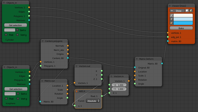
Node diagrams can quickly look busy. To make node diagrams easier to read Frames can be added and named. Select the nodes then "Join in New Frame" from the node menu. The whole frame can then be moved around as one item.
There is also a SV Groups feature on the right hand panel of the Node Editor window. This collapses a number of nodes down to a single node.
Example Image
