I've called this post Shaders for Sverchok and it follows on from my Simple Sverchokseries. It's mostly about Blender Cycles Materials and how I apply them to my Sverchok models rather than directly about Sverchok nodes.
The structures I've been producing with Sverchok can have many elements. The one that featured in the title image for the last post has 2400 copies of the box element. With the position, rotation and scale of each object being varied parametrically it would be neat to also systematically vary the colour or transparency of the elements. Applying individual materials to 2400 elements by hand is well beyond my pain threshold. The techniques used here to make systematic or random material variations can also be used for models with many elements produced in other ways, for example using dupliverts.
Object Info Node
Change the Node Editor window to show Shaders (materials). Make sure Cycles is chosen as the render engine. Start with an "Object Info" node ("Add > Input > Object Info"). This gives information about the object or objects a Material is applied to. If the elements you want to shade are combined into a single mesh they will need to be separated. In edit mode a mesh can be separated into objects by hitting "P" and selecting "By loose parts". It's a good idea to apply a material to the mesh before separating parts. This way all parts will have the same material which can be edited later. It is also possible to separate loose parts using the "Separate Loose Parts" node.
Tip: In Blender if you need to apply the same material to lots of different objects, join them together, apply the material and then separate by parts again.
Location based Shading
The first output of the "Object Info" node is location. This gives the (x, y, z) coordinates of the object the material is applied to. Unfortunately the Shader nodes do not have the wonderfully useful "Viewer text" and "Stethoscope" nodes that Sverchok does. Without these we're running a bit blind and have to read the documentation a bit more and do lots of small bits of math.
If the elements you want to shade were separated from a single mesh they may all have the same location. To fix this, select all the objects and "Object > Transform > Origin to Geometry". This will give each object its own location at the centre of its own mesh.
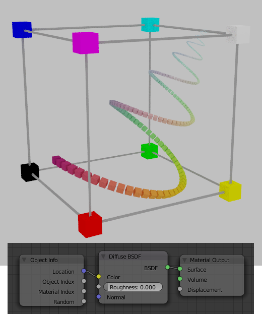
The location of the object can be sent directly to the color input of any shader node. However the shader node expects the RGB values to be between 0 and 1. One easy way to do this is rescale your scene so that all the geometry lies in a box between (0, 0, 0) and (1, 1, 1). The colour of objects in this space will shade from black at the (0, 0, 0) corner to white at the far (1, 1, 1) corner. Objects in the (1, 0, 0) corner will be red and so on. In the following scene all objects have the same material. The wireframe cube extends from (0, 0, 0) to (1, 1, 1). It is a neutral grey colour because its location is (0.5, 0.5, 0.5).
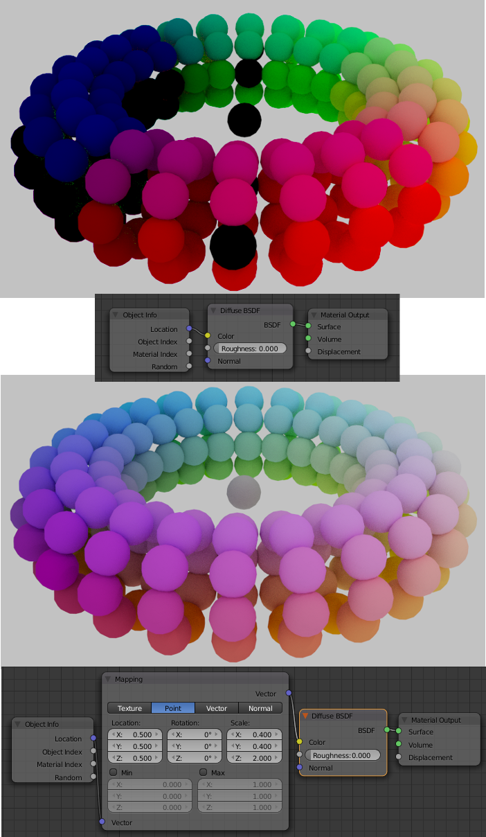
Rather than scaling the geometry to lie within the (0,0,0) to (1,0,0) box we can scale the x, y, z coordinates within our node diagram.
In the following scene the spheres (dupliverted onto a torus) have locations from -1.25 to +1.25 in x and y and from -0.25 to +0.25 in z. We can use the Vector mapping node to transform these location values to the interval (0, 1).
r = 0.4 * x + 0.5
g = 0.4 * x + 0.5
b = 2.0 * x + 0.5
Strange things happen when the rgb values are not within the range (0, 1). The top torus has no scaling bewteen the location and color while the torus on the bottom has the rgb values between (0, 1).
EDIT: Jerryno's answer to my question on stack exchange explains these strange things very well.
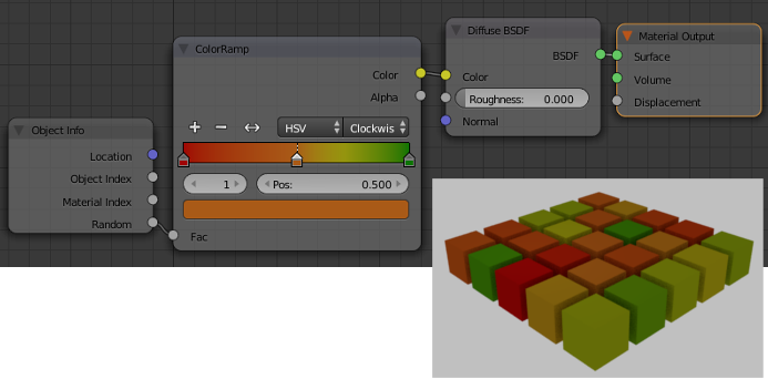
We can also use the location as an index into a "Color Ramp" node. This requires reducing the three x, y, z coordinates to a single value between (0, 1).
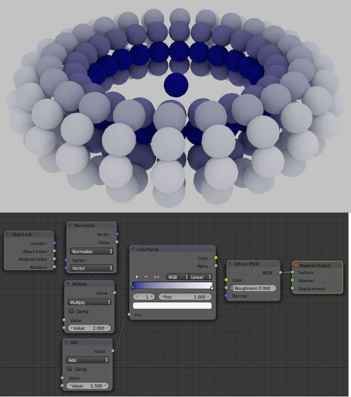
For instance we can shade our torus radially by calculating:
radius = sqrt(x^2 +y^2 + z^2) to give radius between (0.75 and 1.25)

fac = 2*radius - 1.5 to give fac between (0, 1)
These calculations can be done a number of ways. Here I have used the "Normalize" node to give the radius and two "Math" nodes to do the scaling.
Object Pass Index
The second output of the "Object Info" node is labeled "Object Index". This is the same parameter that is called "Pass Index" on the Object Relations Panel. It can be set in the Objects Relations panel or in python using
#set each of the selected objects to a separate pass index
import bpy
for i, obj in enumerate(bpy.context.selected_objects):
     obj.pass_index = i
Again for input to most material nodes the pass index value will need to be scaled so it is in the interval (0, 1).
Material Pass Index
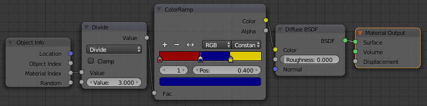
The third output of the "Object Info" node is labeled "Material Index". This output name is a little confusing as Blender has two different pass indexes (object and material) and two different material indexes (the pass index of the material and the material index of a face). Below I give an example of how to use it. It's not that useful for scenes with a large number of objects as it requires a lot of manual steps but I've explained it here because I couldn't find a good example of using the material index of the Object info node anywhere else.
The "Material Index" output of the "Object Info" node is the same parameter that is called "Pass Index" on the Settings panel of a material.
Example use of the "Material Index" of the "Object Info" node.
This uses three materials but of course you can create as many materials as required.
- Start with the default cube scene and set the render engine to cycles.
- Create a node material such as the "mat1" shown below that uses the "Material Index" output of the "Object Info" node.
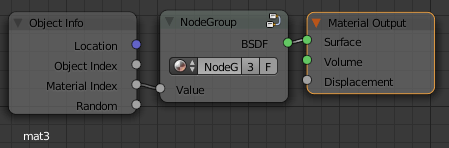
- Select all the nodes except the "Object Info" and "Material Output" and group them
- Use the "go to parent node tree" button at the bottom to collapse the node group. To edit it again click on the button at the top right of the node group
- Select all three nodes showing and copy them to the clipboard (Ctrl-C)
- Create a new material and call it "mat2"
- Delete any nodes in the material and paste (Ctrl-V) our nodes to the material
- Repeat the last two steps labeling the material "mat3"
- You should now have 3 materials that all use the same node group. Check that there is a 3 in the number of users for the node group.
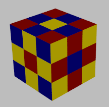
- Select an object and give it three material slots. Place the corresponding material in each slot.
- For each material set the pass index to 1 , 2, or 3. (Under Materials - Settings panel).
- As you do this the small icon beside the material slot should change color to match the color determined by the pass index
- In edit mode select different faces of the object and assign a material from one of the slots.
Random Shading
The fourth output of the "Object Info" node is labeled "Random". It produces a different random number between (0, 1) for each object the material is assigned to.
It can be used directly as input to a "Color Ramp" node or anywhere else a single value is required.