The grid of cells and list of links used as the data structure for 2D mazes by Jamis Buck's in his book "Mazes for Programmers" can be replaced with a mesh object where the vertices are equivalent to cells and the mesh edge connections define the cell neighbors. The maze carving function can then return a subset of the edges that define the path of the maze.
I've implemented this in yet another scripted node (maze_mesh.py) for Sverchok avaliable on github.
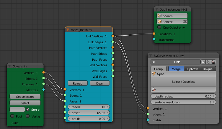
Install the Sverchok addon. Download the maze generation code from github. Then load the python file maze_mesh.py as a text blocks into a blend file. Add a Scripted Node to a Sverchok node tree. On the node select the maze_mesh.py code from the lower drop down. Then click the plugin icon to the right of this field. The node should turn blue with some inputs and outputs.
Path Line generation
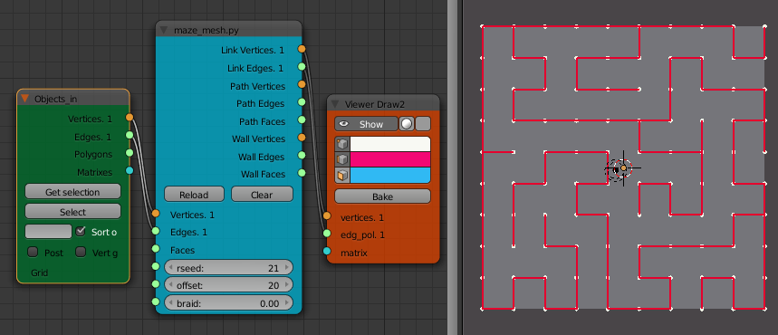
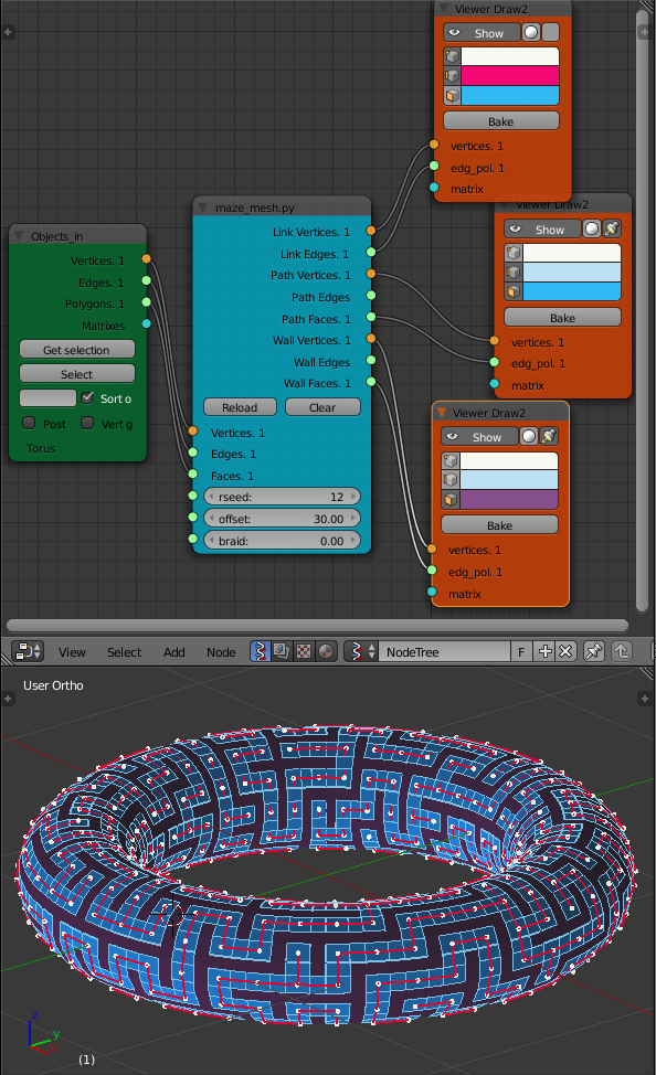
Connect the Vertices and Edges input from a mesh. Connect the Link Verticies and Link Edges to a Viewer Draw node.
This set of verticies and edges without any faces is a bit hard to turn into a good visual representation of a maze. Most of the bevel, solidify or extrude modifiers and nodes need the face informaion to work (the Path, Skin Mesher and Curve Viewer nodes don't require faces and are worth experimenting with).
One way to make a representaion of the maze is to convert the link mesh to a curve (ALT-C) and then apply a bevel to it under the curve property panel. For a non-flat mesh using the Extrude modification or having a bevel obect that isn't an equal size in x and y tends to have odd effects at the link branches.
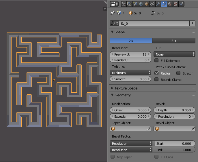
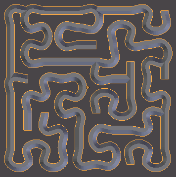
The curve can also be smoothed by converting the Spline Type to Bezier (on the tool panel in edit mode) and setting all the Handles to Auto.
Wall and path generation
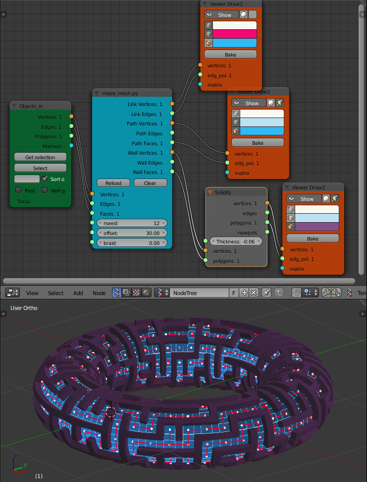
If the scripted node is also provided with the polygons from the mesh, the node will apply an edge bevel to the mesh (this is the same as using CTRL-B on a mesh in edit mode, not to be confused with adding a bevel to a curve as used above). The width of the bevel is set by the offset parameter to be a percent of the adjacent edge length. The node then outputs two subsets of this bevelled mesh. One for the path and one for the walls.
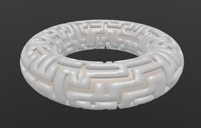
Either the wall or the path faces can be used with a solidify node to produce a maze.

Full 3d Maze
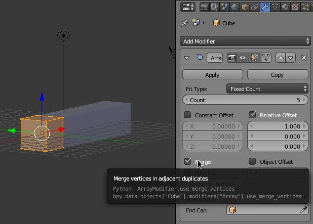
Use the Array Modifier 3 times on the default cube to produce a 3D lattice, at each stage select Merge to merge the vertices of each cube to its neighbor.
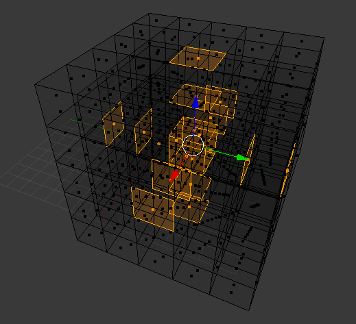
Using the vertices and edges of this mesh as input to the maze_mesh node will give a 3D maze path through the lattice.
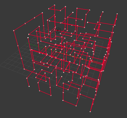
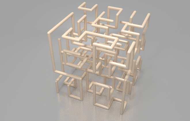
Here I've rendered the maze using the Curve Viewer node to fill the link path and the Dupli Instancer node to fill in the corners with a sphere.
Other Ideas
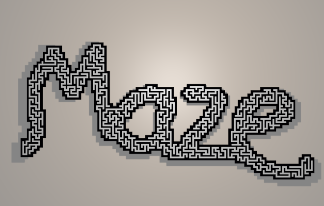
Create an irregular 2d grid maze. Add a fine Grid object, say 100 by 100. Use the circle select tool to draw a shape or word on the grid. Invert the selection and delete the faces. Use this grid as input to the maze_mesh node.