As mentioned in a previous post I've been working on a project to replace the "brain" of a bread-maker with an Arduino.
The aim is to separate out the different stages in the breadmaker's cycle so I can make good sourdough bread. In general the sourdough takes longer to rise than dough made using store bought dried yeast granules. The rise time can also vary depending on how the sourdough starter is on any day. Also the longer the rise time the stronger the sour flavour of the bread.
This project is ongoing. Currently I have made a breadmaker with an Arduino brain where I can set up programs with my own times for any part of the breadmaker cycle. To make a loaf of sourdough, I put the ingredients in the pan and select a program that mixes and kneads the dough then keeps the pan at rise temperature indefinitely. When I've checked the bread is sufficiently risen, I stop that program and run a bake only program. Eventually, I'd like some way of measuring the height of the dough so the Arduino can track when the bread is risen and then switch to the bake cycle. The current rise temperature is the same as for the original breadmaker cycle (~37 °C). I'll probably add an option to rise the bread at a lower temperature for longer to get a stronger sour flavour.
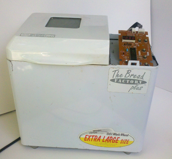
The model of breadmaker I'm using is a fairly old Sanyo "The Bread Factory Plus" (Model SBM-20). From other people's projects I suspect many breadmakers are quite similar internally and these notes could be applicable to many other models and brands.
First of all pull your breadmaker apart to see how it works. Keep all the screws and take photos during the take apart. These are great when you need to put it back together again.
A breadmaker is very simple, it has a motor to turn the paddle and a heater to warm the pan and a thermistor to give the pan's temperature. There's a set of buttons and a display to select a program and start the machine. All this is controlled by a micro controller.
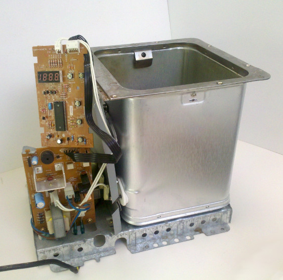
In the above photo the top board contains the buttons, the display and the micro controller. The bottom board controls the motor and heater. This makes our development simple and safe. We can replace the top board where the maximum voltage is 5 V without going any where near the nasty mains voltage on the motor and heater. The 5 pin connector goes from the control board to the lower motor and heater board. The two pin connector goes to the thermistor on the side of the baking area.
For safety don't plug the machine into mains voltage when it looks like the above photo. Instead put it back together as much as possible while still having access to the control board.
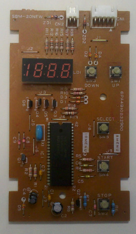
Carefully poking around the 5 pin connector while the breadmaker is going, gives the following designations for the pins. Pin 1 is on the right in the above image.
1 - GND
2 - + 5V
3 - buzzer
4 - heater
5 - motor
Pins 4 and 5 are normally held at 5V but are pulled to GND when the heater or motor are operating. Pin 3 is directly connected to a piezo buzzer.
We can check the temperature sensor is a thermistor by heating the sensor up (disconnected from the board) and reading the resistance between the two contacts with a DVM. The resistance should drop with an increase in temperature. This shows the thermistor has a negative temperature coefficient. The relationship between thermistor resistance and temperature will most likely be non-linear over the range of temperatures (20 °C to 230 °C) we are interested in. We could try and calibrate the thermistor at known temperatures to characterise its temperature versus resistance curve but we really only need to know the resistance at two points, the rising temperature and the baking temperature. We'll find these out by making a loaf of bread while we record what the breadmaker does.
Designing a system to record the bread maker
We will need to design a system to record the heater, motor and thermistor signals while the bread maker makes a loaf of bread. Having done this we can then duplicate those signals with our new Arduino control system.
A thermistor has two connections and is usually read by micro controller using a voltage divider circuit like one of these (the thermistor can either be between the pin and ground or between +5V and the pin):
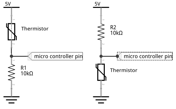
Checking the thermistor circuit shows pin 2 at +5V so we're looking at something like the left most schematic above. However the resistor on Pin 1 of the thermistor is connected to ground via a transistor. The base pin of this transistor is controlled via another micro controller pin. Below is a simplified schematic.
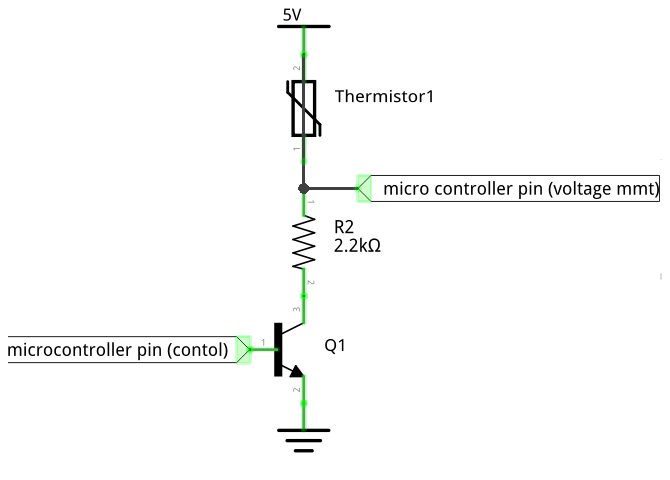
What's happening here is that the micro controller regularly enables the voltage divider via a set of clock pulses sent on the control pin. If we measure the voltage on Pin 1 of the thermistor it will jump between the correct voltage (when the control pin is high) and ground.
This makes the design of the recording system a little bit harder. We could try to synchronize our measurements with the clock signal on the microelectronic but as we're mainly interested in the steady state value of the thermistor at the rise and bake temperatures we can simplify this and use a capacitor to convert the voltage to a steady value.
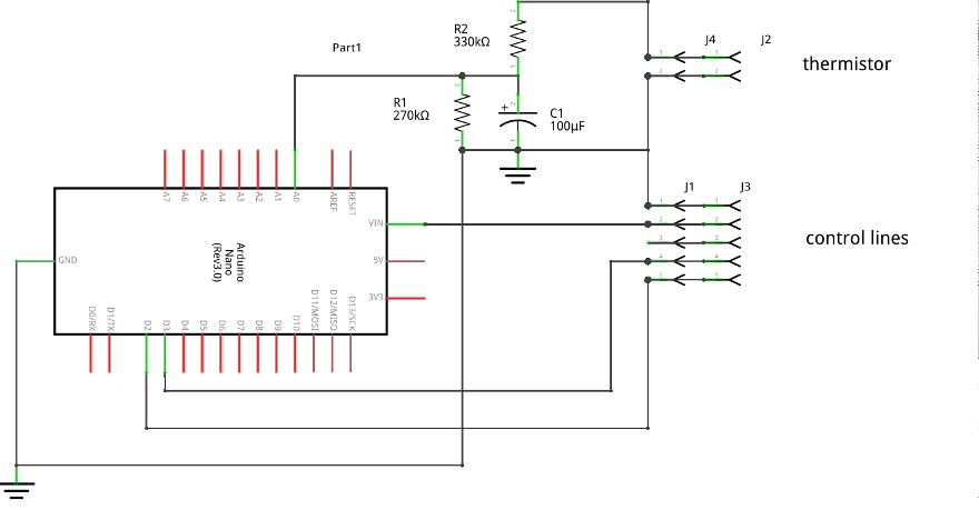
An Arduino can also be used for the recording system. The circuit I used is shown below. As this is only needed once I made it up on a bread board. Keep the original control board connected to the bread maker and add in this recording system to the control and thermistor connectors. Load up the breadmaker_record.ino sketch from the github repository and make a loaf of bread!
Reverse Engineering a control system
The output of the recording system is shown below.

The motor control signals are straight forward. The loaf program starts with 6 minutes of mixing where the motor is pulsed on for ~0.25 second and off for ~1 second. After mixing the bread is kneaded with the motor on continuously for ~29 minutes. There is another two short pulses of the motor about a third of the way through the rising time.
The analog count on pin A0 of the Arduino has an average of 120 during the rising time. For baking it has an average of 330. To convert these counts to resistance values, connect up variable resistor to the recording circuit in place of the thermistor. Vary the resistor to find the resistance values that give analog counts on the Arduino of 120 and 330. Allow enough time after each change in resistance for the count to reach a steady value as the circuit has a long response time due to the large smoothing capacitor.
During the rising time the heater is on for an average 3 seconds and off for 60 seconds. The on cycle varies between 1 second and 10 seconds. The variation in the on cycle time is used to control the temperature.
When the pan is being heated for the baking time the heater is on continuously. During the baking the heater pulses on every 15 seconds with the pulse width again varied to control the temperature. After the baking time the breadmaker keeps the bread pan warm. I haven't yet implemented this keep warm feature in my Arduino program as I don't tend to use it.
Controlling the temperature of the breadmaker with the Arduino consists of reading the temperature sensor (the thermistor) and determining when and for how long to turn on the heater. I avoided getting into most of the complications of control theory by starting with a very simple control algorithm. For example for the rise control:
| Temperature T | time on | time off |
|---|---|---|
| T < tlow | 10 s | 50 s |
| tlow < T < thigh | 6 s | 54 s |
| T > thigh | 1 s | 59 s |
This works well enough because of the long time constant between pulsing the heater and the thermistor responding, the large thermal mass of the system, and the low accuracy (~ +/- 5 °C) required to make bread.
In the control system the thermistor is measured with a simple voltage divider. The motor and heater are controlled via transistors connected to digital lines on the Arduino.
The final circuit is shown below:
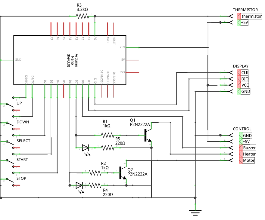
This includes 5 switches to match the switches in use on the original breadmaker and a 4 digit display. The switches use the internal pull-up resistors on the Arduino board and so only need to be connected between the Arduino pin and ground. The 4 digit display is one that includes a TM1637 control chip (for example) and can be controlled from 2 lines on the Arduino. The LEDs in parallel with the transistors are useful for debugging the circuit and program but can be omitted in the final build.
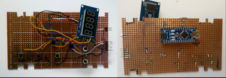
I made the fairly simple circuit board up on a piece of perfboard cut to match the size of the original board. The switches were carefully positioned to be in the same place underneath the pads on the breadmaker cover. The display was hung off the board on longish wires as this was the easiest way to get it to sit underneath the see through area on the cover. The Arduino nano was inserted into headers soldered onto the back of the board. This was to allow easy access for reprogramming.
The full code for the Arduino is available here.
When the bread maker is switched on with its new brain it behaves very much like it used to. Only now it has new programs as defined in the Arduino code. The programs are selected by using the SELECT button to cycle through them. The up and down keys can be used as before to add a delay time to the start of the program. The program is then started with the START button. It can be stopped at any time with the STOP button.
The given Arduino code currently includes the following bread programs:
struct PGRMS
  {
    int min_pulseMix;  // 1/4 second pulse every 1 second
    int min_contMix;   // continuous kneading
    int min_rise1;     // pan kept at rising temperature
    int min_punchDown; // two short mixing pulses
    int min_rise2;     // 2nd rise
    int min_heat;      // pan heated up to bake temperature
    int min_bake;      // pan kept at bake temperature
  };

const int N_PGRMS = 6;

const PGRMS pgrms[N_PGRMS] =
    {
      {6, 29, 30, 1, 53, 8, 42},  // 0 : normal loaf
      {6, 29, 0, 0, 0, 0, 0},     // 1 : mix and knead only
      {0,  0, 1000, 0, 0, 0, 0},  // 2 : very long rise
      {6, 29, 1000, 0, 0, 0, 0},  // 3 : mix, knead and long rise
      {0, 0, 0, 0, 0, 8, 42},     // 4 : bake only
      {3,  3, 10, 0,  0, 0,  0},  // 5 : test nonsense
    };
The first program pgrms[0] bakes an ordinary loaf of bread, mixing it for 6 minutes, kneading for 29 minutes, rising for 30 mintute. Then it quickly "punches down" the bread (two short mixing pulse) and rises the bread for another 53 minutes. Then it heats the pan up and bakes the bread for 42 minutes. Any part of the program can be skipped by setting its value to zero.
Add another program by increasing N_PGRMS and adding a line to PGRMS with the correct times for each part of the cycle.
The next thing I'd like to add to this project is a sensor to determine when the bread is risen. Either a simple optical beam break when the bread reaches the top of the pan or some way of measuring the height of the dough. Choice of sensors will be limited by the high temperatures the breadmaker reaches. But for now my re-brained bread maker makes a pretty good loaf of bread.